
Why Error Codes Aren't Enough to Isolate a Fault
Understand why an error code may have several causes, how test evidence separates them, and what suspect, indeterminate, good, and bad mean in a diagnostic model.
- Author
- Remy InfoSource Pte Ltd
- Published
- Reading time
- 4 min
- Fault Isolation
- Model-Based Diagnostics
What an error code actually tells you
An error code is evidence that a monitored condition crossed a threshold, a required response did not occur, or a self-test detected something unexpected. That evidence can be valuable. It may identify the affected function and the operating state in which the problem appeared.
It does not necessarily identify the failed component.
Suppose a controller reports insufficient flow after issuing a pump command. The controller may know that the reported flow is too low. It may not know whether the pump lacked power, a switching device failed, a mechanical path was blocked, or the sensor reported the wrong value.
Some equipment does produce codes that isolate a particular failure mode very well. The point is not to disregard codes; it is to understand the scope of each code's evidence and avoid treating a symptom-level code as a component-level verdict.
One symptom can have several plausible causes
Illustrative example, not a product-specific error code or customer case. A pump system reports “expected flow not reached.” The code makes a useful starting observation, but several hypotheses remain.
| Candidate cause | Why it could explain the same observation |
|---|---|
| Upstream power-path fault | The pump may not receive usable energy. |
| Switched drive-path fault | A valid command may not reach the pump as the required input. |
| Pump assembly fault | Valid inputs may not produce the intended mechanical response. |
| Blocked or restricted fluid path | The pump may operate without producing the expected flow. |
| Measurement-path fault | Actual flow may differ from the value reported to the controller. |
A replacement instruction that ignores these alternatives can lead to a good pump being removed while the original fault remains. Conversely, assuming that the sensor is wrong without checking it can conceal a real loss of flow.
The next diagnostic step is to find evidence that separates these explanations. Tests should be defined for the actual equipment, its operating conditions, and its safety requirements—not improvised from this table.
Use a model to add context to the code
A component model connects the observed symptom to the functions that could influence it. Test results can then narrow the candidates instead of leaving the technician with a flat list of possible replacements.
For example, an independently verified flow measurement can distinguish a reporting problem from an actual loss of flow. A valid supply-path test can address an upstream electrical hypothesis. Evidence about the commanded input and the pump's response can then help distinguish the drive path from the assembly.
The order depends on access, risk, and diagnostic value. A model should also recognize when a test result is not interpretable because its required inputs or operating conditions are missing.
For the underlying reasoning, see what model-based diagnostics is. The classic first-principles diagnosis paper by Raymond Reiter describes the relationship between system knowledge, observations, and competing diagnoses.
Read diagnostic colors as evidence states
In the iTech diagnostic view, the color meanings are:
| Color | Meaning | How to interpret it |
|---|---|---|
| Yellow | Suspect | The component remains a possible contributor to the current problem. It is not yet confirmed bad. |
| Blue | Indeterminate or off path | Its state cannot be determined from the current evidence, or it is outside the current problem path. |
| Green | Good | The evidence supports the component's good state for the relevant modeled function and conditions. |
| Red | Bad | The evidence identifies a bad state at the model's diagnostic resolution. |
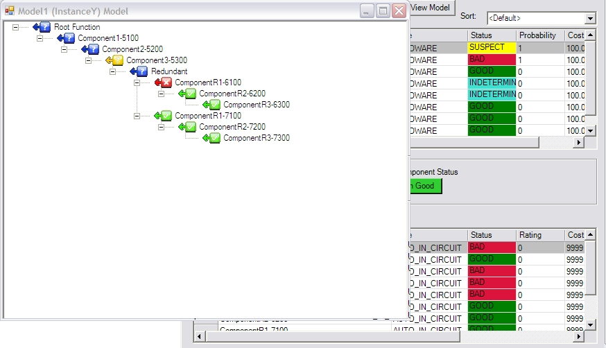
Blue deserves particular care. A downstream component may be indeterminate because an upstream test is bad, leaving the downstream component without the input needed to assess it. Blue can also represent a component outside the current fault path. Neither case is a reason to replace that component.
Likewise, green is not a lifetime guarantee of every function, and yellow is not a repair authorization. Interpret a color alongside the test history, operating conditions, and model boundary. The screenshot illustrates the interface; it is not a record of the hypothetical pump example.
Choose a test that changes the decision
A useful next test has a defined outcome and distinguishes between remaining candidates. Before selecting it, ask:
- What specific hypotheses will a pass or fail address?
- Are the test's prerequisite conditions satisfied?
- Can the result be trusted, including the sensor or human observation used?
- Is there a safer or less disruptive way to obtain equivalent evidence?
- What remains unresolved after either outcome?
Repeating the same unreliable reading does not necessarily add information. Neither does checking a downstream function whose upstream inputs are already known to be absent.
If no available test can separate two candidates, record that limitation and escalate through the approved procedure. Design-for-testability work can address the missing access or evidence in the next product revision.
Keep the code, but improve the reasoning around it
Error codes, test procedures, and diagnostic models complement one another. A code describes what the equipment observed; a model helps explain which component states are compatible with that observation; a procedure defines how to collect the next valid piece of evidence.
The practical objective is not more codes or more colors. It is a defensible decision about what to test, what is still uncertain, and when the evidence supports a repair.
Read reducing MTTR without replacing good parts for the service implications, or request an iTech demonstration to discuss a diagnostic model for your equipment.